IT'S ALIVE!!


The connections have been made and some simple software has been written to map keys to notes. There are some issues that need to be sorted like transpose while pressing keys etc. The concept works! It is a very nice and cheap way to experiment with such a keyboard.

It feels a little flimsy though, pressing buttons against an unsupported perfboard so the top priority now is to find a case that will make the keyboard right at home! I will add some knobs too. There is much (programming) space for them

So, stay tuned for a first video demo as soon as possible. The only thing I need right now, is a little practice!
Posted by Picasa

The proof of concept

This is the keyboard from the last post with some additional stuff. There is a Core module (midibox.org) and a digital in midibox module that reads the switches. I installed the SDK so I can write a minimal program (midibox is programmed in C and produces hex files, uploadable as system exclusive data to the core). So I connected 4 of the switches to make a quick test and connected them all together. I was sure that both midibox modules were ok because I had the midibox sequencer running on them. The simplistic program just adds 40 to the pin number (the one displayed on the LCD) and outputs this as a note on/off midi signal. When all switches get connected, there will be a need for a mapping between module pins and note numbers so there will be some more programming. For now, a small, quickly made video shows that IT WORKS!

(first video for public viewing, so don't be so harsh :)


You can also see it in vimeo here: http://vimeo.com/2357167

Harmonic table keyboard


This is another project I just started working on. It is a keyboard/MIDI controler based on the harmonic table (like the c-thru music controler). This one is just switches which all connect to a midi core module (from ucapps.de) which translates the various keypresses to midi signals. There are 50 keys/notes and although I'm going to use letra-set rub-ons to write the notes onto the keys, you can make out which note is which from the blue keys. They are in pairs and one of each pair (the low/right) is an A (La for europeans) and the other is a C (Do). In the harmonic table layout that the C-thru axis uses (and others) , if you choose one button, the button above it is a fifth, the one to the top/right a minor third and the top/left a major third. (you can see c-thru's chord calculator here http://www.c-thru-music.com/cgi/?page=layout_ccalc).

The other keys have the following functions: The red keys on Braska's left "hand" are a row of 11 buttons that instantly transpose
the whole keyboard from -6 to +5 semitones The middle one, a bit spaced appart, is the no-transpose button. The other 2 red buttons are octave up/down and there is a generic slider under his right hand which is assignable to modulation, pitch bend or whatever CC you want. The blue button under his belly is the menu button. There is a 16x2 LCD screen displaying various bits (transpose, octave, pressed key etc) but the software is still in development stage. As soon as a workable version is at hand, I will publish it of course.

The needed hardware is a lot of switches, a midibox core module, an analog in module (for the slider) and two digital in modules for the switches. I have these already made for the midibox sequencer (who still lacks a panel) until I etch some more. http://synth-diy.blogspot.com/2008/10/midibox-sequencer-v33.html


So the following days will hopefuly see a working HT controller. But until then, good night, Braska!

STAY AT 440 Hz!!!!
Posted by Picasa

Braska explains the midi thru schematic

 
Posted by Picasa


Ribbit....................

Midi Thru Box


I desperately needed some through ports for devices I have that have only in and out ports. So this easy project was done in a single worknight (after putting kids to sleep, 2 hours at most)

It is no compicated design. You just have to get the midi input (using the optocoupler like all midi stuff I've made. Based on ucapps.de midibox design). Then buffering it through two subsequent logic inversions of the signal. One of the outputs goes to the LED for visual feedback. The others, like any midi output fed from 5V, gets a 220Ohm resistor and it is imediately made an output.


I will post schematic later in the day because I have to scan it and I'm too lazy to make it on eagle (it is on paper). If there is a need for a PCB (even though it is a very easy project) I can provide one. I may even make it on a pcb with multiple in/outs (3 in / 9 out eg :)


Say hello to my model: His name is Braska and will be posing on my stuff from now on! He is a cute guy and posing is the only chance to take a break from being beaten, tortured and gummed to death by the kids.
Posted by Picasa

Modular synth PSU

Went today to the shop to get many 150k and 75k resistors to finish the AVRSynth32 but they didn't have enough. My eye caught this fine toroidal transformer of 50VA (I know it is overkill!!!) that outputs +15V, -15V and common ground. So I decided that since I am going to build some yusynth modules, I should have a PSU at hand when the time comes.


The design followed is like the ones of ken stone and ray wilson (PSUs are not THAT complex) so for more info you can go here and here. Cautions apply as you will be working with lethal currents if you decide to build such thing. A note to perfboard makers like myself. The pinout of 79xx is DIFFERENT of the 78XX. For some, this may seem obvious, but for others, if they dont pay attention to the pinouts, they have surprises coming! The regulator might get extra hot and/or explode. Had done this some time ago with a 5v regulator (7905) and when I "checked" it if it was hot (using my finger) I left my fingerprints on the regulator (along with some skin layers that got roasted).

Making it on a perfboard is very simple but BEFORE you plug it, use your multimeter to search for any shorts that might damage the circuit and use a fuse on the mains part of the transformer.


As all sites that have such projects mention:

Disclaimer

A note to readers:

All electronic projects and designs presented on this web site, or associated web sites should be considered dangerous if not lethal if not used safely. When working on projects based on these designs, use extreme care to ensure that you do not come into contact with mains AC voltages or high voltage DC. If you are not confident about working with mains voltages, or high voltages, or you are not legally allowed to work with mains voltages, or high voltages, you are advised not to attempt work on them. The author, host, and all people associated with these web pages disclaim any liability for damages should anyone be killed or injured while working on these projects, or projects based on these designs, or any other project or design presented on these web pages and any associated web pages. The author, host, and all people associated with these web pages also disclaim any liability for projects, or projects based on these designs, or any other project or design presented on these web pages and any associated web pages when used in such a way as to infringe relevant government regulations and by-laws.

(this also taken from ken stone's modular synth pages)
Posted by Picasa

AVRSynth board update

This is a first step towards completing the board. The odd part is that one of the ICs is soldered on the bottom side. This was a clever thought Collin had as it reduces bridges to 5 total from at least 15. As I realized yesterday, I had put no values to most of the components, so tonight, an updated version of the board will be placed online with the values written.


Not all R2R resistors are in place as I ran out of them. So it might be finished tonight. The thing is that soldering resistor ladders is SOOOO BOOOOORRIIINNGGGG!! I should have used a resistor array.


Another thing I should mention is that the board can work with both AVRSyn 16 and AVRSyn 32 firmwares and processors. So I placed a female pinheader in the place of the crystal and I can test both of them before commiting to AVRSyn 32 and it's 16MHz crystal


Hope to have updates soon....
Posted by Picasa

AVRSynth 32 PCB

Collin Mel and myself , have designed a PCB layout for AVRSynth, instead of doing it on perfboard. It hasn't been proofed and debugged yet but I am on the process. If you feel adventurous and/or lucky, you can download the eagle files from here
and try yourself!. Please do tell me about possible bugs you may encounter.

I exposed the photosensitive board covered with a transparency with the PCB layout printed on. I used two transparencies, one stacked on top of the other for extra opaqueness. Still there is a little UV light going through, you may see it on the photos as the copper is a little spotty. No electrical flaws though, but I think, another layer would do a better job.
I developed the exposed board with a solution of 1 teaspoon of pipe cleaner (branded TUB.O.FLO locally) but which contains NaOH. When developed, I etched it using a 14% HCl solution (also a cleaning product) and dropped in it a small cup of concentrated Peroxide. (Named localy "Peridrol"). If interested I can delve in much more detail on the etching process. Just be ware of the fumes and liquids, so work in a well ventilated area, stay AWAY from children (you and the chemicals) and store them out of their reach. These chemicals are highly toxic and caustic and I don't want to be held responsible for any misusage of the components.


This is how it looks while ethcing.. Beware of them bubbles. They stink and for a reason. DO NOT inhale close to them.


This is the finished PCB, without any components on it. I will post photos of the component mounting process and hope it works the first time :)

When this is finished, a core midibox module will take care of the midi messages that are needed to have access to the AVRSynth32 functions that are not available through it's pots. (such as cutoff, resonance, ADSR params etc.)

AVRSynth 16 Panel


The AVRSynth has officially its panel. Drilled on a 3mm aluminum sheet sized at 27x21cm (almost an A4). It was a little difficult to correctly align the holes when drilling them because the drill bit had a tendency to drift off and walk away. The result was a random offset of each hole at about 1mm (in random directions that is.).


Nevertheless, a panel I had made earlier was printed on photographic paper. To align these two, I punched small holes at the centers of the knob positions and turned it facing down (the paper) so I could see through the aluminum holes that it was all aligned (or at least there were no big offsets). I glued it with simple roll on glue and transfered the buttons and knobs from the cardboard panel they were on, to the aluminum one. Now it is a little mess underneath the panel but nevertheless everything works as planed.

I passed it's output through MC-909 effects and it sounds wonderful. Even raw, it sounds pretty nice. I might make a demo with sounds coming out of the AVRSynth 16.

The svg file for the panel layout is here

Stay tuned for updates on the AVRSynth 32 + midibox project.


A family photo (extra members not shown :)

Switches!!!!

Switches came. Tact switches for many purposes... The midibox Seq waits for some of them. The c-music axis clone, for most of them, and maybe a mini keyboard for one of the synths. Hey you could even make a guitar fretboard with them, they are just the right size.


For making stuff with switches, midibox ruleZ!!!!
Posted by Picasa

An AVRSynth 16 layout


I made a layout to be printed on photopaper and be glued on an aluminum panel. I can't process the aluminum sheet by myself so I resort to glueing photopapers allover the place. :) So,
this is it, it has 8 knobs, 16 switches and volume/power and it will be ready with pots on sometime in this week.

You can find the original svg (made with inkscape) at the file repository here

babyBotte repackaged!


This is the new babyBotte. I decided against the cardboard shoebox and dumped it. So I got a 
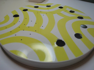
TRIPP container set from IKEA at first for putting the babybotte on the small square one and an 8MHz avrSynth I have lying around, inside the bigger one. My wife gave the idea of putting the babyBotte inside the round one.. So, I designed a panel that I would print on photographic paper and stick it on top of the lid and open holes to it to insert the pots


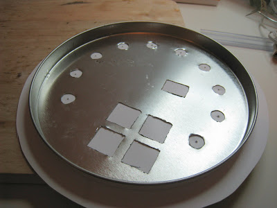
The small holes are for the square buttons. I used a high speed cutter to make the rectangle cuts.

Also, because the box was a bit high to grip it easily, I marked it at about the middle and cut it with tin scissors (the TRIPPs are made of a rather thin aluminum sheet)


and then I cut the rectangle holes:


To align the holes with the printed layout, I printed a draft, black and white copy of the layout and stuck it on the lid. Then, using that as a guide, I opened small holes which little by little I opened them to the diameter of the pot shafts (10mm in my case).

The layout of the buttons and the panel "design" is available at the file repository (here) .

Then I opened small holes on the printed paper and alligned the holes while letting the glue set.


Using an exacto knife, I opened the holes on the paper


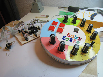
and put pots and switches:


The (still) tricky part was to mount the led. I fixed it with hot glue. It is a bit flimsy but I do not intent to take the babyBote v2 to any live gigs.

So the finished bb was something like that:


or like that

.

The samples still remain the same as the bb survived the move.

The only thing that remains to be seen is the durability of the photopaper..